中文简体
中文简体 русский
 عربى
عربى

Content
- 1 Step 1: Check Thermal Uniformity Across the Web Width
- 2 Step 2: Confirm Tension Balance and Roller Alignment
- 3 Step 3: Verify Draw Ratio and Speed Matching
- 4 Step 4: Rule Out Raw Material and Feed Variability
- 5 A Field-Tested Troubleshooting Sequence
- 6 Verify the Fix with Real Tensile Data
- 7 Prevention: Line Design and Maintenance Habits
- 8 Frequently Asked Questions
- 8.1 What is the first thing to check when geogrid stretching becomes uneven?
- 8.2 How much tensile strength variation across the width is acceptable?
- 8.3 Should I adjust temperature or draw ratio first?
- 8.4 Why are the edges of my geogrid always thinner than the center?
- 8.5 Can uneven stretching affect long-term geogrid performance in the field?
- 9 The Bottom Line: Measure, Adjust, Verify
A roll of geogrid leaves the line looking smooth and even, but the tensile report shows strength dropping from 84 kN/m at the edges to 66 kN/m at the center, with aperture shapes skewed across the width. That is uneven stretching in geogrid production — a defect that hides behind a normal-looking web and quietly weakens everything built with it.
In more than two decades of building and commissioning geogrid lines, one practical rule holds up: uneven stretching is almost never a single dramatic failure. It is a gradual imbalance among four controllable variables — thermal uniformity across the web, tension distribution and roller alignment, draw ratio and speed matching, and raw material consistency. Troubleshoot in that order, measure before you change anything, and let the tensile test report — not the sound of the line — tell you when the problem is really solved.
Step 1: Check Thermal Uniformity Across the Web Width
Polypropylene and polyethylene respond directly to temperature. A 3–5°C difference across the web width changes how much the polymer chains orient, so the sheet draws differently at the edges than in the center. Thermal imbalance is the most frequent cause of uneven stretching complaints on both uniaxial and biaxial lines.
Verify the heating profile with a calibrated surface pyrometer at five points across the web — both edges, both quarter points, and the center — not just the HMI reading. Then inspect air distribution: clogged filters, blocked nozzles, or a damaged insulation blanket create cold streaks invisible from the control panel. Also check for asymmetric edge heat loss; many lines run consistently colder at one edge because of a worn seal or an open access door.
If the profile is flat and stretching is still uneven, move to mechanics. Our guide to uniform heating and extrusion during longitudinal stretching walks through the heater and extruder checks in more detail.
Step 2: Confirm Tension Balance and Roller Alignment
With the temperature profile flat, the next suspects are tension gradients. A roller misaligned by as little as 0.5 mm, a worn bearing on one side, or a nip pressure difference between the two ends of the same roller creates a measurable tension difference across the web — and the stretching process amplifies it.
| Checkpoint | Target | Verification method |
|---|---|---|
| Unwind tension per end | Within ±3% of the average | Handheld tension meter across all ends |
| Nip pressure, left vs. right side | Within 5% | Pressure gauges on both sides of each nip |
| Roller parallelism | ≤ 0.2 mm over 1 m of roller length | Precision level or laser alignment tool |
| Clip chain and bearing wear | No visible pitch elongation | Caliper measurement over 10 consecutive chain pitches |
Run these checks on a regular schedule — monthly at minimum for continuous production — and log the results. Tension and alignment problems rarely appear suddenly; they accumulate until the tensile report shows a pattern.
Step 3: Verify Draw Ratio and Speed Matching
On a uniaxial line, the longitudinal draw ratio equals the take-off speed divided by the feed speed; a 5.5:1 ratio means the fast rollers run 5.5 times faster than the feed rolls. On a biaxial line, the transverse chain speed must match the output of the longitudinal section. When those speeds drift apart, the sheet either over-stretches or relaxes, producing irregular apertures and inconsistent strength.
Check the HMI’s actual speed readings against setpoints rather than trusting the setpoint values. Drive encoders drift, and a 1–2% speed difference between adjacent stretching stations changes the effective ratio more than most operators expect. For biaxial lines, the interaction between longitudinal and transverse stretching deserves its own check — our analysis of longitudinal and transverse stretching uniformity and accuracy covers the common failure modes.
| Parameter | Tolerance | Action threshold |
|---|---|---|
| Draw ratio deviation from setpoint | Within 1% | Recalibrate the drive encoder |
| Speed difference between adjacent stations | Within 2% | Inspect gearbox, coupling, and drive chain |
| Transverse vs. longitudinal output mismatch | Within 1.5% | Recalculate chain speed setpoint |
The chart shows a typical correction: tensile values scattered between 65 and 78 kN/m across the width tightened to 82–84 kN/m after the speed mismatch was fixed.
On older or refurbished lines, the mechanical tolerance of stretching stations may be too loose no matter how well you tune them. A line built for the process, such as the uniaxial tensile geogrid production line, matches drive and stretching sections from design onward.
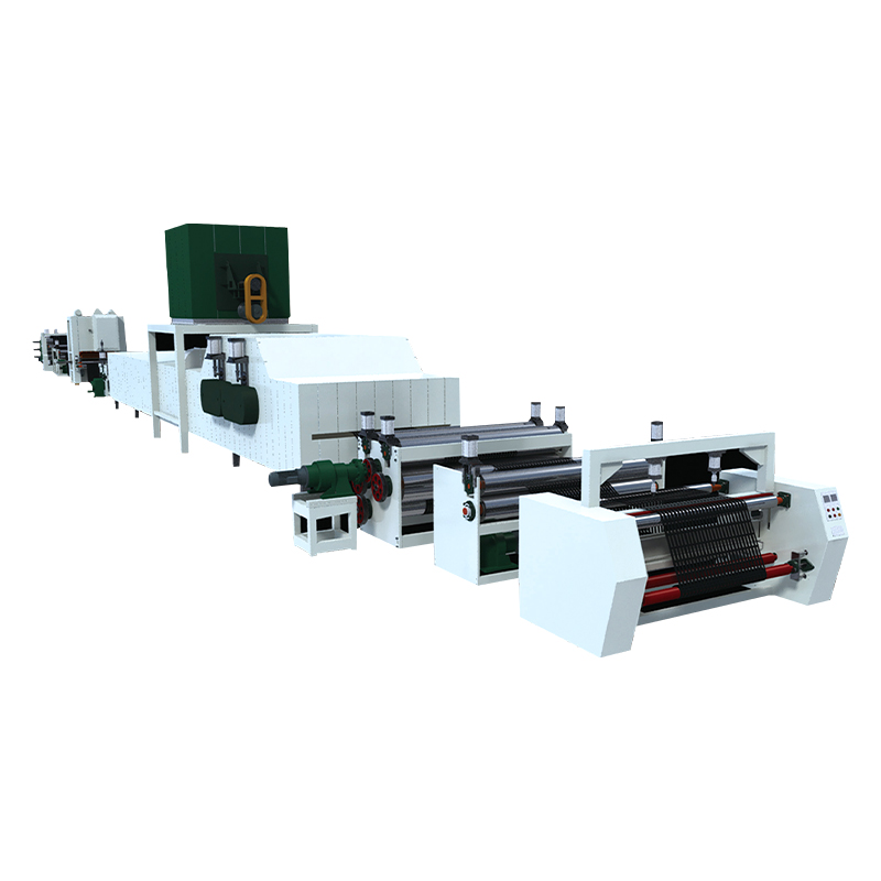 Uniaxial Tensile Geogrid Production Line with Matched Stretching SectionsThis production line integrates drive and stretching stations from design onward, helping reduce unevenness on older or refurbished lines. It is relevant when mechanical tolerance limits sheet quality.View Product →
Step 4: Rule Out Raw Material and Feed Variability
The stretcher amplifies what the extruder delivers. If melt flow index varies between resin batches, if regrind makes up a large share of the feed, or if moisture is not removed consistently, the sheet’s local thickness and melt strength change — and stretching turns those small variations into visible unevenness.
- Keep the regrind ratio stable and screened; 20–30% is a common operating ceiling.
- Dry hygroscopic material consistently; moisture spikes change draw behavior unpredictably.
- Test incoming resin MFI per batch and separate lots when the MFI spread exceeds your specification.
- Watch extruder screw speed and melt temperature; pulsating output creates periodic thickness bands that stretching magnifies.
Raw material issues often masquerade as machine problems because they appear in the same symptoms. That is why material checks belong in the sequence before you start replacing rollers or changing speeds.
A Field-Tested Troubleshooting Sequence
Across installations, uneven stretching root causes distribute roughly as shown below. Use it to prioritize your investigation, not to skip measurements.
- Thermal uniformity — 45%
- Tension and alignment — 25%
- Draw ratio and speeds — 20%
- Raw material feed — 10%
Then run the sequence in this order, changing one variable at a time:
- Record actual speeds, draw ratios, and temperatures from the HMI; compare against the last known-good process setup.
- Measure the web temperature at five positions across the width at the stretching entry; investigate any gradient above 3°C.
- Check nip pressures and roller leveling at the pre-stretch and stretching rollers.
- Measure individual end tension at the creel or unwind stand; flag any end more than 5% above its neighbors.
- Take a full-width sample and test tensile strength, elongation, and aperture dimensions at five positions.
- Change only one variable — never temperature and ratio together — then re-test before the next adjustment.
- Compare results against the previous ten rolls to spot gradual drift rather than acting on one bad sample.
Verify the Fix with Real Tensile Data
Uneven stretching is fixed only when the report says so. A practical acceptance rule for geogrid is tensile strength variation within ±10% of the average across five test positions across the width, with elongation at break inside the same band. High-performance reinforcement specifications often hold ±5%.
| Parameter | Acceptance limit | Test layout |
|---|---|---|
| Tensile strength variation across width | Within ±10% of average | 5 positions: edges, quarter points, center |
| Elongation at break variation | Within ±10% of average | Same 5 positions |
| Aperture diagonal deviation | Within 3% of target | 10 apertures sampled across the roll |
| Thickness variation | Within 5% of average | Micrometer at 5 positions |
That makes the tensile tester a production tool, not a lab afterthought. A dedicated geotextile strength machine with recorded multi-point results gives you the data to confirm repairs, compare shifts, and document batch quality for customers.
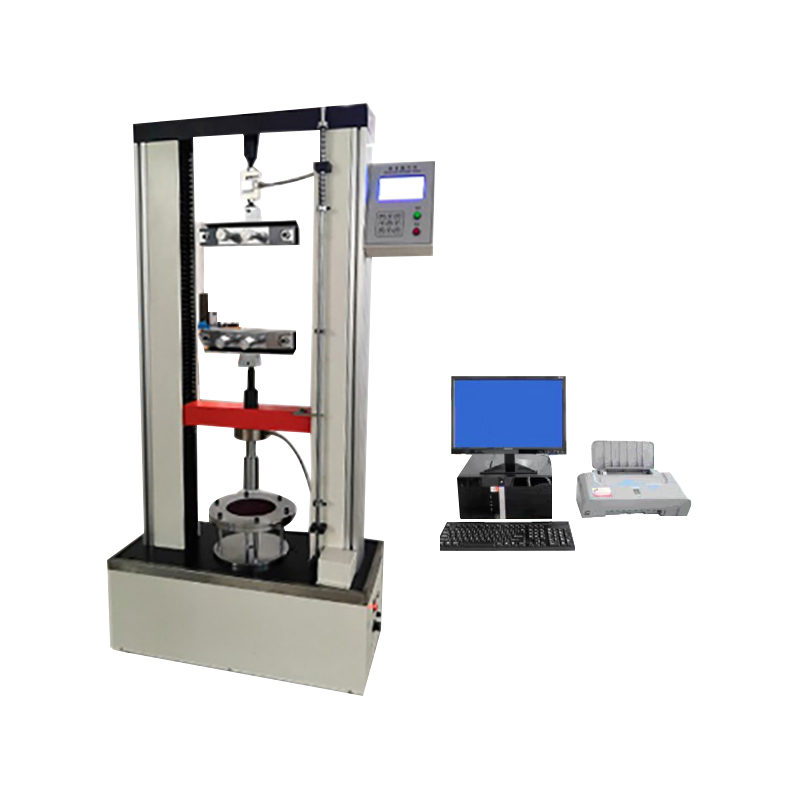 Geotextile Strength Machine with Multi-Point Recording and Computer ControlThis tensile tester records multi-point results and dynamic curves, making it a practical production tool for verifying repairs and documenting batch quality. Its high-precision sensor supports consistent measurement.View Product →
Also track aperture geometry: measure the diagonal lengths of a sample of apertures across the roll. If the diagonals deviate more than a few percent from the target, stretching remains uneven even if the strength numbers pass.
Prevention: Line Design and Maintenance Habits
Prevention beats troubleshooting. Lines with multi-zone PID temperature control, independent nip pressure adjustment on each roller end, precision-ground rollers, and synchronized drives rarely develop uneven stretching in the first place. These features are the difference between a line that needs constant babysitting and one that holds its profile roll after roll.
Maintenance habits matter equally: monthly alignment checks, calibrated temperature sensors at least twice a year, and immediate attention to bearing noise or nip gauge drift. The rollers, chains, and clips that carry the web through the stretching zone are the mechanical heart of the line.
When stretching sections are engineered as an integrated system, problems like uneven stretching get designed out before the first roll is produced. The bidirectional geogrid production line from Jiangsu Saide Machinery is an example — heating, stretching, and drive sections are matched during design rather than patched together on the production floor.
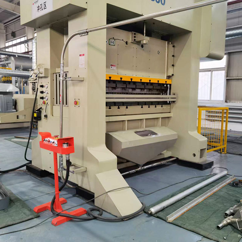 Bidirectional Geogrid Production Line with Integrated Heating and StretchingThis line matches heating, stretching, and drive sections as an integrated system, reducing uneven stretching issues before production. Its design includes a transverse stretching oven and special fixtures.View Product →
Frequently Asked Questions
What is the first thing to check when geogrid stretching becomes uneven?
Measure the temperature profile across the web at the stretching entry instead of trusting heater setpoints. Temperature gradients above 3–5°C across the width are the most common root cause and should be eliminated before touching draw ratios or speeds.
How much tensile strength variation across the width is acceptable?
For most geogrid specs, ±10% of the average tensile strength across five test positions is a practical limit. High-performance reinforcement projects often require ±5%.
Should I adjust temperature or draw ratio first?
Temperature first. Polymer draw behavior is highly temperature-sensitive, so a 3°C cold streak changes local stretching more than a small ratio adjustment. Changing the ratio while a thermal imbalance exists usually masks the real cause.
Why are the edges of my geogrid always thinner than the center?
Edge thinning usually points to faster cooling or higher local tension at the edges during longitudinal stretching, sometimes combined with a draw ratio too aggressive for the actual edge temperature. Check edge heater output, edge cooling air, and edge nip pressure.
Can uneven stretching affect long-term geogrid performance in the field?
Yes. Under-stretched zones retain lower molecular orientation and weaker creep resistance under sustained loads; over-stretched zones become brittle and damage easily during handling. Irregular aperture geometry also makes soil interlock and overlap splicing less predictable.
The Bottom Line: Measure, Adjust, Verify
Uneven stretching in geogrid production is solvable when you replace guesses with measurements. Thermal profile, tension balance, draw ratio and speed matching, and raw material consistency cover nearly every case you will meet. Build a verification routine, keep records, and train operators to read the tensile report as carefully as they read the line display.